In the increasingly widespread application of RFID technology today, whether it is a hotel key card, an access control system, or retail supply chain management, RFID antenna design and debugging are key to ensuring the stable operation of the system. However, many engineers in the RFID antenna debugging process often encounter a variety of problems, that not only waste a lot of time but also may lead to substandard product performance. This article will analyse the RFID antenna design and debugging of common errors, and provide effective solutions to help you save up to 90% of the debugging time.
The Importance of RFID Antenna Commissioning
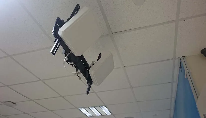
The core of the RFID system lies in the wireless communication between the reader and label, and the antenna is the bridge of this communication, its performance directly determines the reading distance, stability and anti-interference ability of the system. A well-designed RFID antenna system can significantly improve the recognition rate, reduce misreading, and maintain stable work in complex environments.
However, because RFID antennae involve electromagnetic field theory, circuit design communication protocols and other aspects of knowledge, debugging process errors are often difficult to locate quickly. According to statistics, about 40% of the time RFID system development is used for antenna debugging, and 80% of these problems stem from several types of common errors. Mastering the characteristics of these errors and solutions will significantly improve the development efficiency.
Common RFID Antenna Errors and Their Impact

The following are the most common types of errors in RFID antenna design and commissioning, and their impact on system performance and commissioning efficiency:
Circuit Matching Errors
Circuit matching is the most basic and error-prone part of RFID antenna design. Correctly matched circuits can ensure efficient energy transmission, while incorrect matching will lead to signal reflection, and energy loss, and ultimately affect the reading distance and stability.
Typical circuit matching errors include:
- Improper LC matching: improper selection of parameters of L2, L3, C25, C30 and other components in the antenna matching circuit, resulting in impedance mismatch
- Component package selection error: such as the use of 0603 package 2.2uF inductor rather than a larger package, resulting in the actual parameters and design values deviating too much.
- Insufficient antenna voltage: the voltage at the TP38 test point is lower than 15V, which can’t generate a strong enough communication carrier.
This type of error usually leads to a 30-50% increase in debugging time, while the correct practice is to ensure that the P-P value is in the range of 15-30 V, with an ideal value of about 20 V. By accurately adjusting the parameters of the matching circuits, the performance of the system can be significantly improved and the debugging time can be reduced.
Modulation Depth Errors
Modulation depth is a key indicator of RFID communication quality, which directly affects the signal recognizability and anti-jamming ability. Improper modulation depth will cause the reader to be unable to correctly demodulate the signal, thus triggering communication failure.
Common modulation depth errors include:
- Modulation depth beyond the standard range: the normal range should be 8% ~ 14%, beyond this range will lead to communication instability
- Modulation parameter setting error: GsnReg, CwgsReg, ModgspReg and other registers are not set properly.
Practice shows that the ideal modulation depth is about 13.8% (e.g., 180mv/(740+560)mv=13.8%), within which the system has the best communication distance and stability. Correctly setting the modulation parameters can reduce the debugging time by 15-35%.
Initialization Parameter Errors
RFID reader initialization parameter settings are the premise of the normal operation of the system, the wrong initialization parameters will lead to the entire communication process can not be established normally.
Common initialization parameter errors include:
- ASK modulation parameter error: disable ASK should be set to 100%, otherwise it will affect the modulation effect
- Transmit/Receive Mode Error: TxmodeReg should be set to 3, and RxmodeReg should be set to 0x0b.
- Type register error: TypeReg should be set to 0, otherwise the card type will be incorrectly recognized.
This type of error usually increases the debugging time by 15-40%, while correct initialization parameter settings can ensure that the system works in the best state from the very beginning.
Communication Protocol Errors
RFID systems work on the basis of strict communication protocols, such as the ISO/IEC 14443 standard. Protocol errors can lead to communication failures between the reader and the tag, manifested as failure to recognize the card or incorrect data transmission.
Typical communication protocol errors include:
- CRC checksum problem: some chips need to add CRC checksum, and some do not need it, the wrong CRC processing will lead to communication interruptions
- Command format errors: such as REQB, ATTRIB and other command formats do not comply with the 14443_3B communication protocol specification.
- Wrong time slot setting: In a multi-card environment, improper time slot setting can lead to frequent conflicts.
This type of error usually increases the debugging time by 20-45%, and strict adherence to the protocol specification can avoid most of the communication problems.
Antenna Design Errors
The physical design of the antenna is the basis of system performance, and an unreasonable design can radically limit the potential of the system.
Common antenna design errors include:
- Unreasonable antenna shape: does not conform to the electromagnetic field distribution law, resulting in inefficient signal transmission and reception
- Inappropriate antenna location: unreasonable relative position, creating interference or blind spots
- Wrong antenna size: does not comply with the standards defined by ISO/IEC14443, resulting in an operating frequency shift
These types of errors are often the most difficult to correct and can increase debugging time by 30-60%, or even require hardware redesign. Therefore, antenna design should be done in strict accordance with the standards at the early stage of design.
RFID Antenna Common Errors Comparison Table
| Error Type | Specific error | Consequence | Debugging time-consuming impact | Solution |
| Circuit Matching Error | Improper matching of LC | Antenna can not work properly, reading distance shortened | Increase 30-50% of debugging time | Adjust L2, L3, C25, C30 parameters to ensure that the TP38 voltage > 15V |
| Component package selection error | Circuit performance is not stable, parameter drift | Increase 20-40% debugging time | Select the appropriate package, such as 2.2uF need to use a large package | |
| Insufficient antenna voltage | Communication carrier modulation failure | Increase 25-45% debugging time | Ensure that the P-P value is in the range of 15~30V, the ideal value is about 20V | |
| Modulation Depth Error | Modulation depth out of range | Short reading distance, unstable communication | Increase 15-35% of debugging time | Keep the modulation depth between 8%~14% |
| Modulation parameter setting error | Poor signal quality, high BER | Increase 10-30% debugging time | Correct setting of GsnReg, CwgsReg, ModgspReg and other registers | |
| Wrong Initialization Parameters | Wrong ASK modulation parameters | Cannot recognize the card correctly | Increase 20-40% debugging time | Set disable ASK to 100% |
| Transmit/receive mode error | Communication unidirectional or complete failure | Increase debugging time by 15-35% | Correctly set TxmodeReg=3, RxmodeReg=0x0b | |
| Type register error | Card type recognition error | Increase debugging time by 10-25% | Make sure TypeReg is set to 0 | |
| Communication Protocol Error | CRC checksum problems | Packets are rejected and communication is interrupted | Increase debugging time by 25-45 | Depending on chip type, decide whether to add CRC checksums or not |
| Command format error | Card does not respond or responds incorrectly | Increase 20-40% debugging time | Strictly follow 14443 protocol format | |
| Incorrect time slot setting | Frequent conflicts in multi-card environment | Increase 15-30% debugging time | Correctly set time slot parameters | |
| Antenna Design Error | Unreasonable antenna shape | Low efficiency of signal transmission and reception | Increase 30-60% commissioning time | Follow ISO/IEC14443 standard to design antenna shape |
| Inappropriate antenna position | Uneven reading area, more blind zones | Increase 20-40% commissioning time | Optimize antenna relative position to reduce interference | |
| Wrong antenna size | Operating frequency shift, performance degradation | Increase 25-50% commissioning time | Strictly follow the standard design antenna |
Best Practices for Efficient RFID Antenna Commissioning
To avoid the above common mistakes and to significantly improve debugging efficiency, we recommend the following best practices:
Systematic Debugging Flow
Establishing a clear debugging process and debugging in the order of “circuit matching→initialization parameters→modulation depth→communication protocol” can avoid mutual interference and improve positioning efficiency.
Use of Professional Test Equipment
Oscilloscopes, spectrum analyzers and special RFID testers are essential tools. Through these devices can visualize the signal waveform, measure the modulation depth, and quickly locate the problem.
Parametric Debugging Method
Adopting a parametric debugging method, i.e., adjusting only one parameter at a time and observing its effect on system performance, can avoid mutual interference of multiple factors and improve debugging efficiency.
Establishment of Parameter Templates
For different types of RFID application scenarios, establish standard parameter templates, including matching circuit parameters, initialization parameters modulation parameters, etc., which can significantly reduce repeated debugging work.
Modular Design Idea
The RFID system is divided into the antenna, matching circuit, control circuit and other modules, independent testing of the performance of each module, you can quickly locate the module where the problem is, to avoid repeated debugging of the whole system.
Conclusion
By adopting a systematic debugging process, using professional test equipment, applying parametric debugging methods, establishing parameter templates and implementing modular design, these errors can be effectively avoided and the development efficiency and product quality of RFID systems can be significantly improved.
In practice, different RFID products may face different challenges, but by mastering these basic principles, you can comfortably cope with a variety of complex situations, to ensure the stable and reliable operation of the RFID system. By reducing debugging time, companies can accelerate the speed to market, reduce development costs and improve market competitiveness.
With rich experience in RFID product development and debugging, RFIDLabel can provide customers with all-around technical support from design to production, help customers avoid common mistakes and quickly realise high-quality RFID solutions.